Technical Information
Home
AM Basics & Station Setup
Class E Overview and
Theory of Operation
Output Circuit Values & MOSFET ratings
High Power & Harmonic Reduction
Device Protection
Testing & Tuning Procedures
Modulators & Power Supplies
Design Tools
Construction Projects
Construction Overview
Simple 400 Watt
RF Amp for
80 meters
VFO for 160 & 80 meters
Using a lower power
transmitter as an
RF source (A to D converter)
Pulse Width Modulator and power supply
24 MOSFET RF Amplifier - Step by Step
Analog Modulator (Class H) and power supply
Overall Schematic of a complete modulator/power supply
Class E Kits
and Parts

Technical Support
|
.
|
|| Class E Home
|| WA1QIX home page
|| QuickEasy Logger Page
|| Class E Forum
|| AMFone
||
|
|
.
The Two Module, 300 to 500 Watt RF Amplifier for 160 and 80 Meters
 This Class E RF amplifier will deliver between 300 and 500 watts of RF, depending
on the input voltage and tuning parameters (current). The amplifier uses
two DEIC420 Driver ICs (one per module), and is easily band switched between
160 and 75 meters using relays. Transient Voltage Supressors (TVS devices) are
used on the gate bus, drain bus and modulated DC input to the RF amplifier to
protect the MOSFETs from damage due to accidental overvoltage. The carrier
DC voltage should be between 40 volts and 50 volts, and no more than 130 volts at
full positive peak modulation.
This Class E RF amplifier will deliver between 300 and 500 watts of RF, depending
on the input voltage and tuning parameters (current). The amplifier uses
two DEIC420 Driver ICs (one per module), and is easily band switched between
160 and 75 meters using relays. Transient Voltage Supressors (TVS devices) are
used on the gate bus, drain bus and modulated DC input to the RF amplifier to
protect the MOSFETs from damage due to accidental overvoltage. The carrier
DC voltage should be between 40 volts and 50 volts, and no more than 130 volts at
full positive peak modulation.
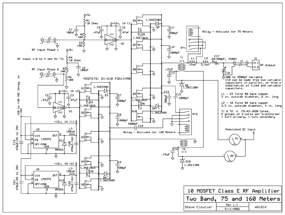
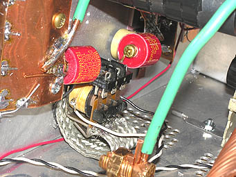
Construction Notes: The shunt capacitors C7, C8 and C9 along with C11, C12 and C14
do not have to be individual capacitors. You could use a single 2000pF
capacitor of a sufficient current rating (6 amperes or more is recommended). The
design called for 2000pF of capacitance, and these were the values I had on
hand at the time. Two 1000pF capacitors would work just as well as the two
500pF and single 1000pF shown in the circuit. The reason at least two capacitors should
be used is to get a higher current rating, and to distribute the RF current
between multiple devices. Otherwise, the shunt capacitor is simple multiple
capacitors in parallel.
This 10 MOSFET RF amplifier consists of two identical 5 MOSFET RF
amplifier stages connected together in a single ended push pull configuration.
Each amplifier stage (module) is driven by a single DEIC420 Drive IC. The
driver ICs take a standard TTL (5V) input, and each IC is driven out of phase
with the other, so when one is "on" the other is "off". The
outputs are also combined out of phase, giving the single ended, push pull
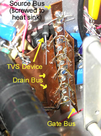
configuration. TVS (TransZorb) devices are used on the drain and gate busses, and on the modulated
DC input to each amplifier stage.
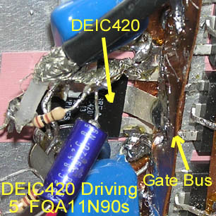
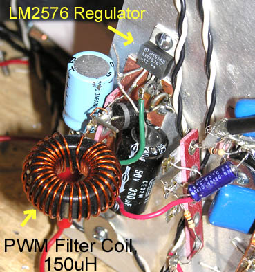
Driver
 The transmitter uses the DEIC420 driver IC, one for each module.
Each driver IC has its own LM2576 +12V switching regulator. The LM2576 can deliver
up to 3 amperes of DC at 12V - more than enough current for the DCIC420 on 75
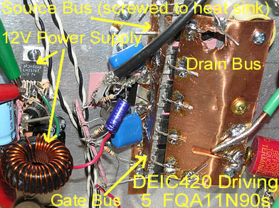
and 160 meters. The output terminal (a wide, flat silver plated lead)
of each of the driver ICs should be directly soldered to the gate
bus of the respective module, at the center. The ground terminals of
each driver IC are connected directly to the source bus, and two bypass
capacitors are used on the +12V DC input for each IC. The TTL input to the
drivers is delivered via 50 ohm coax cable (RG58 or similar 50 ohm thin cable),
and each cable is terminated by a 100 ohm resistor to ground and a 100 ohm
resistor to a bypassed (at the IC) +5V source.
The transmitter uses the DEIC420 driver IC, one for each module.
Each driver IC has its own LM2576 +12V switching regulator. The LM2576 can deliver
up to 3 amperes of DC at 12V - more than enough current for the DCIC420 on 75
and 160 meters. The output terminal (a wide, flat silver plated lead)
of each of the driver ICs should be directly soldered to the gate
bus of the respective module, at the center. The ground terminals of
each driver IC are connected directly to the source bus, and two bypass
capacitors are used on the +12V DC input for each IC. The TTL input to the
drivers is delivered via 50 ohm coax cable (RG58 or similar 50 ohm thin cable),
and each cable is terminated by a 100 ohm resistor to ground and a 100 ohm
resistor to a bypassed (at the IC) +5V source.
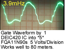 The gate waveform produced by the DEIC420 driver is
very good on 75 meters, and approaches
a true square wave on 160 meters. This results
in a very stable and efficient class E amplifier.
- - -
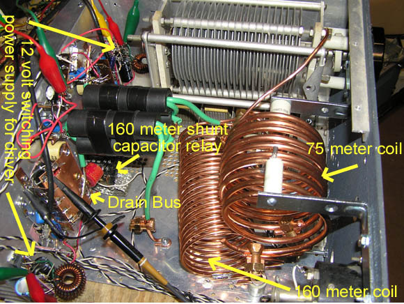
Band Switching
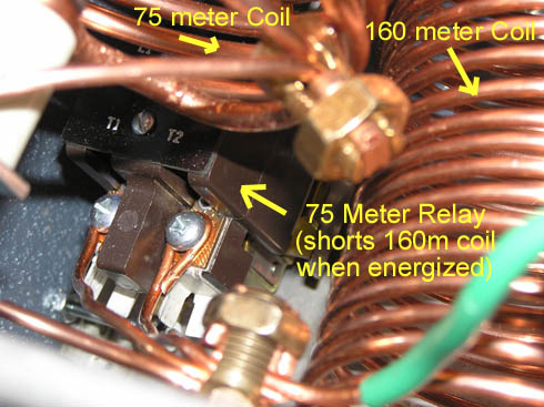 Relays RY1 and RY2 are used for bandswitching between 160 meters and 75 meters.
When using the RF amplifier on the 75 meter band, relay RY1 is activated,
shorting out the 160 meter coil. Relay RY2 is open, removing the extra shunt
capacitance needed for 160 meters from the circuit. On 160 meters, relay RY1
is opened, putting the 160 meter tank coil in series with the 75 meter tank.
Relay RY2 is energized, adding another 1200pF of shunt capacitance to
each RF amplifier, as required for 160 meter operation. The frequency of
the RF voltage fed to the Schmidt trigger / phase splitter must also be
switched to the appropriate band.
Relays RY1 and RY2 are used for bandswitching between 160 meters and 75 meters.
When using the RF amplifier on the 75 meter band, relay RY1 is activated,
shorting out the 160 meter coil. Relay RY2 is open, removing the extra shunt
capacitance needed for 160 meters from the circuit. On 160 meters, relay RY1
is opened, putting the 160 meter tank coil in series with the 75 meter tank.
Relay RY2 is energized, adding another 1200pF of shunt capacitance to
each RF amplifier, as required for 160 meter operation. The frequency of
the RF voltage fed to the Schmidt trigger / phase splitter must also be
switched to the appropriate band.
|