Home
Class E Overview and
Theory of Operation
Output Circuit Values & MOSFET ratings
High Power & Harmonic Reduction
Construction Overview
Simple 400 Watt
RF Amp for
80 meters
Using a lower power
transmitter as an
RF source (A to D converter)
Pulse Width Modulator and power supply
24 MOSFET RF Amplifier - Step by Step
Analog Modulator (Class H) and power supply
Overall Schematic of a complete modulator/power supply
![]()
Construction Tips and OverviewNote: Important Safety Notice! Please read it :-)
Special tools you will probably need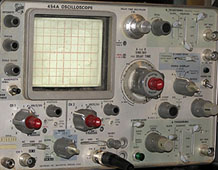 Building a class E transmitter is not particularly difficult, however there
are some tools, both electronic and otherwise, that you will need to have.
It will be difficult, although not impossible, to build a class E transmitter
without an oscilloscope. You need to have access to a good 50 mHz or better oscilloscope!
You will need a decent 'scope to really ensure that your
transmitter is working correctly, and for testing various parts of the transmitter
as construction proceeds.
Building a class E transmitter is not particularly difficult, however there
are some tools, both electronic and otherwise, that you will need to have.
It will be difficult, although not impossible, to build a class E transmitter
without an oscilloscope. You need to have access to a good 50 mHz or better oscilloscope!
You will need a decent 'scope to really ensure that your
transmitter is working correctly, and for testing various parts of the transmitter
as construction proceeds.
|
|
Drills, taps and dies. You will need a drill with an assortment of bits. A tap and die set is really nice. Tapping holes into heat sinks for mounting of MOSFETs and transistors is a little time consuming, but it sure makes things easier in the long run with respect to mounting devices. A Variac (variable autotransformer) is strongly recommended for bringing things for the first time, and for making adjustments while testing. It can save many many hours of time. Of course, you will need the normal assortment of tools (screwdrivers, wrenches, pliars, etc), and at least one, if more, volt-ohm-milliampmeter(s). |
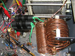
Special Parts - Coils, Capacitors and OthersClass E transmitters, like most high power RF amplifiers, require some large RF components. The RF tank coil should be made out of very heavy wire. For transmitters up to 400 watts or so, coils for 40 meters should be made from #4 bare copper or copper tubing. On 75 meters, #4 bare copper works very well, and is readily available from handyman supply stores. On 160 meters, the coil can be safely wound from #8 bare copper. Connections to the coils can be made using large split bolts or other solderless connectors.The series tuning capacitor (used in the tank of most of the class E transmitters shown here) must be a high voltage, high current, air variable or vacuum variable capacitor. These capacitors are available from a number of sources. Multi band operationThe subject of operating class E amplifiers on multiple bands had been the subject of considerable attention over the years. Several amateurs have built class E RF amplifiers spanning more than one band. Others have constructed seperate RF amplifiers for each band, and switched between them, using a single modulator and power supply for everything. Both have their advantages.Bandswitching a single RF amplifier
Relay switching is generally the most practical way of switching the various RF components. Switching shunt capacitors must be done with care, using short, thick, heavy leads, and preferably contactors that do not contain any internal wiring. This will keep the inductance of the shunt capacitor switching system as low as possible. It is better to use seperate inductors for each band, connected in series, and short-circuited when not in use than to use a single inductor with shorted turns. The shorted turns get hot due to very high circulating current, and this can waste considerable power. This high current also flows through relays, switches and the like, heating these components as well. |
|
Switching between multiple RF amplifiers for each band Switching between multiple RF amplifiers is easier to accomplish, and generally will give better results, as each amplifier is optimized for the band in question. Seperate RF amplifiers also results in a more flexible setup. It will also, in general, remove the need for retuning when changin bands - the RF amplifier will usually be tuned up from the last use. The disadvanages of using seperate RF amplifiers are greater space and increased cost, as parts such as tuning capacitors and heat sinks are needed for each RF amplifier. It is generally easier to set up all of the metering required (drain current meters, voltage meters, etc.) as part of the modulator / power supply, and switch the modulator output between the various RF amplifiers. Use heavy relays or a high current switch for this purpose. What to buildRF AmplifierSeveral transmitters are presented at this site. The 400 watt transmitter for 75 meters is a fairly simple transmitter to construct. The physical layout is compact and easy to build. This RF amplifier is a balanced design that reduces harmonic output, and is very stable. ModulatorsModulators fall into two general classes - Analog and Digital (pulse width). Both have advantages. The analog modulators will operate over a wider range of load currents and resistances, and are generally fairly straight-forward in design. The primary disadvantages of analog modulators are the size and weight. Analog modulators are much larger than comparable digital (pulse width) modulators, and have significantly large power supply requirements.Digital (pulse width) modulators are the most efficient (up to 95% efficiency is possible), and can be made smaller, and require smaller and simpler power supplies than comparable analog modulators. Pulse width modulators are designed to work into a particular load resistance - the load in this case being the class E RF amplifier. The class E amplifier must be operated within certain parameters to properly match the design impedance of the modulator. Digital modulators are designed with significant filtering, by the nature of how they work, and therefore can offer better control over the transmitted bandwidth than analog modulators. The Pulse Width Modulator and Power Supply is probably the best modulator choice, as there are printed circuit boards available to facilitate construction of the low level circuitry, and the design includes many advanced features. |
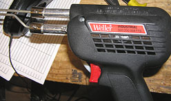 Class E transmitters generally contain heavy conductive buses, usually made of copper. These
are very hard to solder without a lot of heat. You will need to have
a very heavy duty soldering gun.
I tend to recommend the Weller D650 industrial soldering gun. It's heavy duty,
and produces enough heat to solder any drain, gate or source bus I've created so far.
Class E transmitters generally contain heavy conductive buses, usually made of copper. These
are very hard to solder without a lot of heat. You will need to have
a very heavy duty soldering gun.
I tend to recommend the Weller D650 industrial soldering gun. It's heavy duty,
and produces enough heat to solder any drain, gate or source bus I've created so far.
 Switching a single class E amplifier between bands will usually result in a
smaller overall transmitter than that obtained by switching between multiple
RF amplifiers, and
components such as the tuning capacitor need only be purchased once. The
trade off is more difficult construction and design. It is highly recommended,
if you are going to build a multi band RF ampflier, to use a broadband driver
circuit using driver ICs or some other non-resonant design. This will remove
the necessity of changing or switching components within the driver when changing bands.
Switching between two bands is generally reasonable to accomplish. Switching
between three bands is more challenging.
Switching a single class E amplifier between bands will usually result in a
smaller overall transmitter than that obtained by switching between multiple
RF amplifiers, and
components such as the tuning capacitor need only be purchased once. The
trade off is more difficult construction and design. It is highly recommended,
if you are going to build a multi band RF ampflier, to use a broadband driver
circuit using driver ICs or some other non-resonant design. This will remove
the necessity of changing or switching components within the driver when changing bands.
Switching between two bands is generally reasonable to accomplish. Switching
between three bands is more challenging.