Home
Class E Overview and
Theory of Operation
Output Circuit Values & MOSFET ratings
High Power & Harmonic Reduction
Construction Overview
Simple 400 Watt
RF Amp for
80 meters
Using a lower power
transmitter as an
RF source (A to D converter)
Pulse Width Modulator and power supply
24 MOSFET RF Amplifier - Step by Step
Analog Modulator (Class H) and power supply
Overall Schematic of a complete modulator/power supply
![]()
-
Modularization
|
ModularizationModularization involves the use of two or more basic class E RF amplifiers connected to a single output network. Generally, each module will have its own input transformer(s) [or driver ICs if this is used], and output transformer. The voltage outputs of the individual modules add together, and the impedance is similarly multiplied by the number of modules connected in series. If many modules are thus connected, care must be taken to ensure that the wiring used in the output transformers has sufficient insulation to withstand the higher voltage.The power output obtained from an RF amplifier of modular design is equal to the sum of the power output of each of the individual modules. It is possible to combine many modules to form one large RF amplifier. Harmonic ReductionThe output of a standard class E RF amplifier, as delivered to the output network is a very non-symmetrical, harmonic rich waveform. By using an even number of modules, it is possible to configure the amplifier to deliver a symmetrical, rounded waveform to the output network, which contains significantly fewer harmonics.
Note: The modular circuits shown here do not show exact values for some components. I do not have actual values, as I have not personally constructed these exact circuits. You will need to determine the values for the driver transformer by experimentation. You should have at least 12V positive peak (24V peak to peak) at the gates of the RF output MOSFETs. The values shown for the RF output network are approximate, for 75 meter operation. |
Getting Higher Power The easiest way to get higher power with class E amplifiers is to combine
multiple smaller class E amplifiers (modules) together to form one
larger amplifier. An even number of modules should be used, and they
should be configured such that every other module is out of phase with
its neighbor. This will result in low harmonic output, and easier output
network design.
The easiest way to get higher power with class E amplifiers is to combine
multiple smaller class E amplifiers (modules) together to form one
larger amplifier. An even number of modules should be used, and they
should be configured such that every other module is out of phase with
its neighbor. This will result in low harmonic output, and easier output
network design.
The DC drain current of each module should be independently metered. You will not be able to properly balance the current of each stage without proper metering. Each module should include TVS devices across the gate bus, drain bus and modulated DC input.
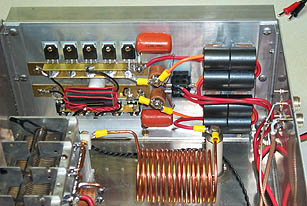
Balancing multi-module class E amplifiersThe dc current of the modules are balanced with respect to each other by ensuring each module is operating in the same (or 180 degrees out of) phase. Small variations in inductance, lead length, input transformers and gate capacitace can effect the phase of the input signals, causing an imbalance. If you are using input transformers, it is usually sufficient to squeeze the turns on the transformer primaries closer together, or spread them apart to achieve balance.If you are using ICs and digital drive (no transformers), provisions should be made in the low level digital circuitry to adjust the balance between out of phase modules. Small variations in phase can be introduced by using slightly longer or shorter lengths of cable connecting the low level circuitry to the driver ICs. The picture to the right shows a class E RF amplifier consisting of 4 modules of 5 MOSFETs per module. The 4 output transformers can be seen in the background, under a plexiglass sheet added for mechanical stability. |
 This is accomplished by connecting the modules out of phase with respect to each other.
The modules are driven out of phase with respect to each other, and the
outputs are also connected out of phase (reverse the secondaries of the RF output
transformerss of every other module). This type of connection is sometimes
called single ended push pull.
When the module or modules in phase "one" are turing on (gates of the MOSFETs
driven positively), the modules in phase "two" are turning off (gates
driven negatively). Each module will produce a standard class E output waveform,
and the output waveforms will be out of phase with each other.
When one module is turing on,
and producing the flat or square portion of the
class E waveform, the other module will be turning off, producing the high output
pulse of the class E waveform. Since the secondaries of the output transformers
are connected in series and out of phase with each other (and the inputs are
being driven out of phase with respect to each other), the resulting waveform
is symmetrical. One module (or set of modules)
will provide the positive portion of the cycle, the
other module or modules pding the negative portion of the cycle.
This is accomplished by connecting the modules out of phase with respect to each other.
The modules are driven out of phase with respect to each other, and the
outputs are also connected out of phase (reverse the secondaries of the RF output
transformerss of every other module). This type of connection is sometimes
called single ended push pull.
When the module or modules in phase "one" are turing on (gates of the MOSFETs
driven positively), the modules in phase "two" are turning off (gates
driven negatively). Each module will produce a standard class E output waveform,
and the output waveforms will be out of phase with each other.
When one module is turing on,
and producing the flat or square portion of the
class E waveform, the other module will be turning off, producing the high output
pulse of the class E waveform. Since the secondaries of the output transformers
are connected in series and out of phase with each other (and the inputs are
being driven out of phase with respect to each other), the resulting waveform
is symmetrical. One module (or set of modules)
will provide the positive portion of the cycle, the
other module or modules pding the negative portion of the cycle.