Home
Class E Overview and
Theory of Operation
Output Circuit Values & MOSFET ratings
High Power & Harmonic Reduction
Construction Overview
Simple 400 Watt
RF Amp for
80 meters
Using a lower power
transmitter as an
RF source (A to D converter)
Pulse Width Modulator and power supply
24 MOSFET RF Amplifier - Step by Step
Analog Modulator (Class H) and power supply
Overall Schematic of a complete modulator/power supply
![]()
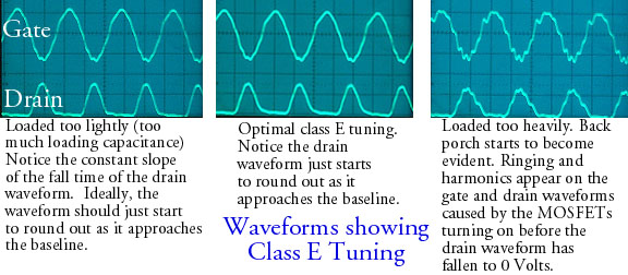
Verifying transmitter operation and tuning it upFirst Time on the Air Tune UpThe first time a class E rig is put into operation, you must use an oscilloscope to ensure everything is working correctly. Do not apply gate drive or any other voltages to your class E transmitter without first connecting an oscilloscope to the stage in question. After proper transmitter operation has been verified, you can tune the transmitter using the drain current meter, output meter and/or efficiency meter. When you first put a transmitter into operation, use this step by step procedure to ensure everything is working. 1) MOSFET Gate Voltage Check the gate waveform(s). Connect the oscilloscope probe between the MOSFET source and gate leads. Connect the scope probe directly to the MOSFETs if possible. If you're using a driver stage, start with the gate of the driver MOSFET, get the driver working correctly, and then move to the final RF amplifier. If the gate waveform is poor, get it right before applying any drain voltage. If you're using a driver, and the gate voltage is OK, apply drain voltage to the driver only, and verify that the proper gate drive is present at the final RF amplifier and that the driver drain current is not excessive. The driver drain voltage waveform may not be a good class E waveform, as the driver is not necessarily operating in class E. If you're using sine wave drive, make sure the waveform is at least close to a sine wave, and not too triangular. Flat topping of the sine wave is OK. You should see something like a 10 to 12 volt positive swing, measured at the gates. 2) Verify the drain waveform Once the gate waveform has been established at the final RF amplifier, connect the 'scope probe to the drain, between the drain and source. If you have a dual trace 'scope, keep one probe on the gates and monitor the gate waveform at the same time you're monitoring the drain waveform. Before applying any drain voltage, set the tuning and loading capacitors all the way "in" (full capacitance). Bring up the drain voltage to 1/3 to 1/2 of the operating voltage (slowly, if possible!). If you don't start drawing excessive current, try (when you get to about 1/3 of the DC operating voltage) adjusting the tuning capacitor and see if you can get something resembling the sample waveform. If you do, great!. If not, try opening up the loading cap a bit. If you cannot get the proper waveform, or at least something which resembles the waveform, you may have too little or too much inductance, and/or too little or WAY too much tuning capacitance. Usually, higher than optimum values for the tuning and loading capacitance will still result in a class E waveform and low relatively low drain current. If the drain voltage is too low to get reasonable drain current, you will not be able to get the proper waveform. The idea behind tuning one of these transmitters correctly is to get
maximum efficiency consistent with the desired output.
Here are some more detailed examples of transmitter tuning waveforms.Ok, you've got something which looks OK on the scope. If you are not already monitoring the gate waveform, check it again with the RF amplifier operating at reduced power. Make sure the gate voltage is still 10 to 12 volts of positive swing. If it's starting to drop off more than a small amount as the drain voltage or current is increased, you might have an input to output coupling problem. Refer to the Gate and Gate Driver section, "Maintaining gate drive under modulation" for tips on correcting the problem. Bring the RF amp up to full voltage, watching the drain waveform on the scope to ensure that the peaks are within safe limits. Now, adjust the loading cap until you start to see some "back porch" or noticeable peaks or spikes showing up on the "low" time of the drain waveform. Watch the drain current - make sure it doesn't get too high. If it does, re-adjust the tuning capacitor to lower the drain current. Once you start to see the back porch on the waveform, back off the loading cap a little, until the wave looks good again. The transmitter is properly adjusted for the power level you're running. If you need more power, adjust the tuning capacitor for lower capacitance - the drain current will go up. If you start to see back porch, ringing, or other spikes starting to show up during the drain waveform "low" increase the loading capacitance. As described above, check the gate voltage and waveform again - under full power. You are properly tuned up when, for a given power level, your loading capacitor is set such that any lower capacitance settings will result in back porch or other anomalies during the drain waveform "low" time. Something to note: The drain waveform will most likely become quite distorted as you drop the drain voltage to very low values. The current and voltage may not track in a perfectly linear fashion once you drop below a certain drain voltage. This is not a big problem. The drain waveform should *not* become distorted as you increase the drain voltage. Record the settings of the tuned elements! 3) Important: Observe the gate and drain waveforms under modulation When applying modulation, do so first with reduced voltage applied - just to make sure the modulator is working at all under low power. Bring up the modulation slowly - whether under reduced or full power. Monitor the drain and gate waveforms under modulation - at the same time, if possible. Look for parasitics, spikes in voltage (above what should be expected) and changes or significant reductions in the gate drive voltage (no more than a volt or so change at full modulation). The gate voltage should not change very much with modulation. TEST, TEST, TEST!!! Tuning without an oscilloscope Tuning with the Drain Current and RF Output MetersOnce you have verified your transmitter operation with an oscilloscope, you should be able to tune the transmitter using the drain current meter, and an RF output indicator (SWR bridge, etc.). With most class E transmitters, the output or "loading" capacitor is generally set for the lowest capacitance consistent with a good waveform. In most instances, there is a peak in the RF output when the optimum value is reached. Further decreases in the output capacitor will result in a lower RF output. The optimum value will be just before the point where the RF output begins to fall off. When tuning up, Operate the RF amplifier no modulation. This is very important, particularly if the transmitter is way out of tune. If the load, for whatever reason, is improper or non-existant, modulating under these conditions could cause a big problem. You do not necessarily need to reduce the DC voltage to the final amplifier, however it is not a bad idea to do so. While monitoring the drain current and the RF output, adjust the capacitance of the tuning capacitor so the drain current is about 1/2 to 2/3 the normal current. You should show some RF output. Check the SWR to verify you have a good load. Now try reducing the capacitance of the loading capacitor. The output should increase (as should the drain current), and at some point while reducing the loading capacitance, the output should begin to fall off. Increase the loading capacitance slightly, so the capacitor is set to the point just before or right at the RF output drop off. Re-adjust the tuning capacitor to obtain the desired drain current. Re-adjust the loading capacitor as necessary. At this point the transmitter should be tuned up. If you tuned with reduced drain voltge, you should be able to apply full drain voltage, and modulation. Re-check the tuning when operating at full power. Using an Efficiency Meter
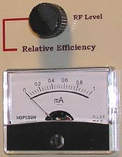
The Efficiency Meter (Patent Pending) (Non commercial, individual use of the circuit and method permitted) is an innovative circuit
that provides an effective and
accurate method of tuning a class E transmitter. The meter compares the
power input of the RF amplifier to the RF output and displays the result
on a panel meter. The RF output voltage is generated by rectifying and filtering
a small portion of the RF output.
Tuning is simply a matter of obtaining the highest indication on the efficiency meter at the desired drain current. Since the RF output from the class E amplifier will change considerably as the optimum tuning point is reached, an RF level control is provided to keep the levels within the indication range of the meter. At optimum tuning, the meter will be sensitive to efficiency changes of under 1%. A PC board implementation of the Efficiency Meter is available. In addition to the Efficiency Meter, the board also contains an overload shutdown system that can be tied into most transmitters, providing very effective protection in the event of an overload. |