Home
Class E Overview and
Theory of Operation
Output Circuit Values & MOSFET ratings
High Power & Harmonic Reduction
Construction Overview
Simple 400 Watt
RF Amp for
80 meters
Using a lower power
transmitter as an
RF source (A to D converter)
Pulse Width Modulator and power supply
24 MOSFET RF Amplifier - Step by Step
Analog Modulator (Class H) and power supply
Overall Schematic of a complete modulator/power supply
![]()
.
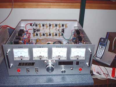
Combination modulator - power supply by Bob, K1KBW. Modulators and AudioIn theory, any type of high level modulator can be used with a class E RF amplifier to form a complete AM transmitter. The modulator can be transformer, series or shunt coupled. However, the best type of modulator to use is some type of series modulator. Such a modulator can use any technology - class A analog, high efficiency analog, or digital (Pulse Width), as long as the result is modulated DC applied to the RF amplifier. By far, the best modulator to use is a pulse width modulator. The power supply requirements are easy to meet, and the modulator offers outstanding audio performance and very high efficiency. Digital (pulse width) modulators are the most efficient (up to 95% efficiency is possible), and can be made smaller, and require smaller and simpler power supplies than comparable analog modulators. Pulse width modulators are designed to work into a particular load resistance - the load in this case being the class E RF amplifier. The class E amplifier must be operated within certain parameters to properly match the design impedance of the modulator. Digital modulators are designed with significant filtering, by the nature of how they work, and therefore can offer better control over the transmitted bandwidth than analog modulators. A properly designed and implemented pulse width modulator can produce broadcast quality audio, and the system is widely used in modern AM broadcast transmitters. How Pulse Width Modulators Work |
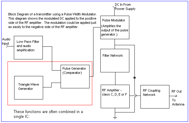
A pulse width modulator is essentially a switching power supply, where the output voltage of the supply can be controlled by an external input. In this case, we feed audio into that input, and control the output of the switching supply with the audio we're supplying. Audio amplifiers using pulse width modulation are becoming quite common, particularly for high power amplifiers. Brief discussion on how Pulse Width Modulators operate Pulse width modulators operate by varying the duty cycle - the "on time" as compared to the "off time " of a switching (square wave) waveform. This switching waveform is produced using relatively simple low level circuits, and is amplified using switching (either saturated or cutoff) amplifier stages, to the desired output voltage. The output of this amplifier is then filtered, removing the switching frequency. After filtering, the output is the average voltage of the switching waveform. By controlling the switching waveform on-time as compared to the off time, we can control the output voltage, after filtering, of the amplifier. Because the amplifier stages in a pulse width modulator are operated either at cutoff or saturation (this is called switch mode, or class D), such modulators are typically very efficient. 95% efficiency is achievable with practical circuits.
More Information about Pulse Width Modulators A complete explanation of Pulse Width Modulators, and how the PWM Modulator works can be found in this Solid State PWM paper. There is also a similar writeup on Vacuum Tube PWM. |
Power Supplies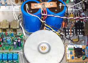 Class E RF amplifiers and their respective modulators require a variety of
DC voltages. Some of these voltages need to be switched on and off, and in
a particular sequence.
Class E RF amplifiers and their respective modulators require a variety of
DC voltages. Some of these voltages need to be switched on and off, and in
a particular sequence.
Providing power to low level circuitsLow voltages such as +12, -12, +5, etc. are easily supplied using standard 7812, 7912, and 7805 linear regulators connected to a transformer/rectifier/filter combination. It is usually advisable to separate the power supplies for various functional units. For instance, the modulator should have its own low voltage power source, independent of any other functional units such as RF amplifiers. Low power supplies should be fused with a small fuse, appropriate for the particular transformer in use.High Voltage, High Current SupplyThe power supply for the final RF and modulator stage will need to supply hundreds of watts of steady-state power, and perhaps thousands of watts of peak power under heavy modulation. Furthermore, this power supply will most likely be switched on (keyed) during transmit, and switched off when in receive mode.Power Supply FilterDue to the relatively high current (low impedance) of most class E transmitters, the power supplies are generally capacitor input filters, and most often this single capacitor is the entire filter. Unless the filter capacitor is excessively large, there will be a small amount of ripple in the output. Generally, the modulator will reduce or eliminate this ripple from the RF output if it is designed correctly.Power TransformerThe volt/amp rating of the transformer and the current rating will determine how much power a transformer can supply. If you have a transformer that can supply 90VAC at 5.5 amperes, you have about a 500 VA transformer. With a capacitor input filter, under load, you can expect to get around 115 VDC from the supply. Even though the transfomer can supply 5.5 amperes, you CANNOT draw 5.5 amperes continuously from the supply at 115VDC because you will be exceeding the power rating of the transformer. Furthermore, the volt ampere rating of the transformer should be reduced somewhat when using a capacitor input filter. The supply in this example should be able to safely provide between 3.5 and 4 amperes of current at 115VDC. Switching the High Voltage SupplyA discharged filter capacitor in a high voltage supply is a virtual short circuit across the supply when it is first energized. There needs to be some amount of resistance in the system, or rectifier failure will eventually result from the current surge. If the power transformer is a very high current transformer and adds very little resistance to the system, some type of step start should be employed. A step start puts a low value resistor in series with the power supply AC input for a short period of time, as the filter bank is charging. The resistor is then shorted out by a relay.The AC input to the supply, as well as the DC output from the supply should both be switched. If the AC input is allowed to remain after the load is removed from the supply, the supply voltage will soar. If the DC output is not switched, you run the risk of a catastrophic failure in your transmitter, as the entire stored energy of the power supply will be discharged into the lowest resistance path of the system. You will also be prevented from using an effective overload system, as these systems rely on the ability of the DC to be quickly removed from the transmitter. Be sure to include a light bleeder resistor to slowly discharge the filter capacitors when the supply is in standby or turned off. It is highly dangerous to allow stored voltage to remain for a long time after a supply is turned off. The switching system should be so designed so as to not enable the high voltage supply unless the low level circuitry is activated and functioning. The Driver should be switched in a manner similar to the RF amplifier. The driver power *must* come from a separate power supply, used only for the driver. If the driver power is derived from the final RF amplifier power supply, you will not be able to effectively test or tune up the transmitter. The output voltage of the supply should be metered at all times, and it is also a good idea to meter the output current. A proper line fuse must be provided for the high voltage supply. Remember, the power supplies used in most class E transmitters produce dangerous voltages!!! Please read the Safety Notice. You cannot be too careful! Power Supply Wiring, Rectifiers and Relays 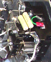 The rectifier should be rated at many times the expected steady state supply
output. If you are building a 20 ampere supply, your rectifier should be at
least a 50 ampere (and perhaps higher) bridge rectifier. The peak rectifier
current is many times the average.
The rectifier should be rated at many times the expected steady state supply
output. If you are building a 20 ampere supply, your rectifier should be at
least a 50 ampere (and perhaps higher) bridge rectifier. The peak rectifier
current is many times the average.
With certain designs and under heavy modulation, the peak current required from the supply is many, many times the average output - in some cases 8 or 10 times as much. As an example, you are using a pulse width modulator modulating a 320 watt class E RF amplifier: 40 volts at 8 amperes. The power supply output voltage is 120 volts DC (as an example). The modulator is 95% efficient, so the steady-state current from the supply is around 2.8 amperes. If the transmitter were suddenly modulated to its full positive peak value, the full supply voltage will, in essence, be supplied to the RF amplifier. The resistance of the RF amplifier is 5 ohms (40 volts divided 8 amperes), so the power supply would be required to deliver 24 amperes (120 volts divided by 5 ohms) for the modulation peak. You should use at least number 12, and preferably number 10 wiring between the supply and the load, and the interconnecting wires should not be too long, as excessive voltage drop will result. Any relays must be able to carry the full, peak current of the supply. Use large, good contactors with heavy terminals and wide contacts. Relays used for DC must be heavier than their AC counterparts, as DC is more difficult to swith, and contact welding and arcing can be a problem. Motor control relays with strong springs work well in this application. |
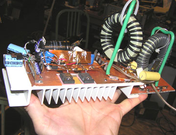 The advent of some very good Pulse Width Modulator ICs over the past few years has significantly
simplified the design and construction of these types of modulators. Excellent
results can be achieved with comparatively few components. The filter network
components are fairly small, at least up to 400 or 500 watts, and it is possible
to build a 400 watt pulse width modulator that you can hold on one hand.
The advent of some very good Pulse Width Modulator ICs over the past few years has significantly
simplified the design and construction of these types of modulators. Excellent
results can be achieved with comparatively few components. The filter network
components are fairly small, at least up to 400 or 500 watts, and it is possible
to build a 400 watt pulse width modulator that you can hold on one hand.