Home
Class E Overview and
Theory of Operation
Output Circuit Values & MOSFET ratings
High Power & Harmonic Reduction
Construction Overview
Simple 400 Watt
RF Amp for
80 meters
Using a lower power
transmitter as an
RF source (A to D converter)
Pulse Width Modulator and power supply
24 MOSFET RF Amplifier - Step by Step
Analog Modulator (Class H) and power supply
Overall Schematic of a complete modulator/power supply
![]()
Amplitude Modulation Amplitude Modulation (AM) is essentially a mixing process where the
audio "modulating" signal is mixed with the radio frequency "carrier".
The resulting signal actually consists of three distinct components:
the carrier, the upper sideband (carrier frequency plus the audio
modulating frequency) and the lower sideband (carrier frequency minus
the audio modulating frequency).
Amplitude Modulation (AM) is essentially a mixing process where the
audio "modulating" signal is mixed with the radio frequency "carrier".
The resulting signal actually consists of three distinct components:
the carrier, the upper sideband (carrier frequency plus the audio
modulating frequency) and the lower sideband (carrier frequency minus
the audio modulating frequency).
One very practical method of generating AM is to vary the DC voltage fed to an RF amplifier that exhibits a square-law characteristic. A square-law simply means the RF amplifier's output power increases as the square of the applied voltage - using Ohm's law:
An amplifier operating in saturated or switching mode (class C, D, E and F are the most common) is well suited to amplitude modulation because these types of amplifiers, when properly adjusted and configured, will exhibit an excellent square-law characteristic.
The diagram above shows the major components of an AM transmitter. The RF amplifier takes input from an RF source and amplifies it to the desired power level. The modulator consists of a high power audio frequency amplifier. It is connected between the RF amplifier and the power supply, and is designed to modulate the DC voltage fed to the RF amplifier. This type of modulator is known as a Series modulator - so named because the modulator is in series with the power supply and the RF amplifier. The modulator may by either analog (class A, G, H, etc.) or pulse width (switching). In an ideal situation, the modulated DC fed to the RF amplifier will exactly match the audio input to the modulator. Several types of series modulators are described here. Setting up a StationIf you are building your first Amateur transmitter, you may have to provide some basic infrastructure, such as a transmit/receive system, audio equipment, a good microphone, monitoring equipment, etc. for your station. Much of this equipment can be built (such as the transmit/receive system, and much of the audio equipment, power supplies, etc.) while other components (such as the microphone, oscilloscope, modulation monitor, etc.) will most likely be purchased as a completed unit. The choice of what equipment to buy and what to build is generally based on the interest and skill of the operator.The most complex piece of equipment in most Amateur stations is the receiver, and few Amateurs elect to build their own receivers. Most people purchase a receiver from a Ham Radio store, local Ham flea market, on-line auctions, or through local "Want Ad" type of publications. These same sources can generally be used to find other related equipment. Music stores are very good sources of microphones and other audio equipment, both new and used.
The diagram above shows a complete station, including the receiver. In some cases, functions may be combined into one unit (such as the modulator and the power supply), but in many cases, each of the blocks shown is a seperate unit. The choice of what (if any) blocks to combine is largely a matter of practicality and personal choice. Generally, it is not a good idea to combine high power RF circuitry with any kind of low level audio circuitry, as the audio circuits will often "pick up", or detect and demodulate the RF energy. This will cause serious problems such as distortion, feedback, parasitic oscillations and other undesired effects. If a functional unit can be used for several purposes (such as one modulator / power supply with several RF amplifiers), that unit (or combination of units) need only be built once, with provisions made for switching among other parts of the overall system. The Transmit/Receive System (Important!)While not particularly difficult to accomplish, care must be taken to ensure the proper switching sequence of antenna, transmitter and receiver. If the system is not properly designed and built, it may be possible for the transmitter to be producing output power, while the antenna is in the process of switching from receive to transmit, or visa versa.A proper sequencer should be used for ALL amateur stations, not just stations running class E transmitters. Proper sequencing ensures that everything is in a known state before transitioning from receive to transmit, and back to receive again. The switching sequence of operations is different when going from transmit to receive than it is when going from receive to transmit. When going from receive to transmit, the following sequence should be used:
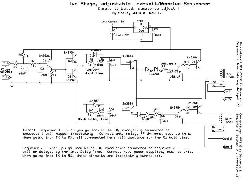
A full size PDF of this sequencer circuit is Here (sequencer circuit pdf) |
Audio Processing, Equalization, Microphones, and other Equipment If the you are building a transmitter that does not include audio processing circuitry, your setup must
include some type of external audio processing equipment. At minimum this should include:
If the you are building a transmitter that does not include audio processing circuitry, your setup must
include some type of external audio processing equipment. At minimum this should include:
Microphones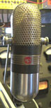 A good microphone is essential to good audio quality. Good does not have
to mean expensive! Electret condenser elements are available for only a few dollars.
These little gems generally sound wonderful, if properly connected and physically mounted.
It is of absolute importance that you provide a good wind screen when
using a condenser microphone of any kind. Even a small breath pop will generate
a great deal of output, and will cause distortion, excessive noise on the signal, and
seriously impair the sound.
A good microphone is essential to good audio quality. Good does not have
to mean expensive! Electret condenser elements are available for only a few dollars.
These little gems generally sound wonderful, if properly connected and physically mounted.
It is of absolute importance that you provide a good wind screen when
using a condenser microphone of any kind. Even a small breath pop will generate
a great deal of output, and will cause distortion, excessive noise on the signal, and
seriously impair the sound.
There are several very good commercial condenser microphones available. Marshall and Behringer both make a high quality microphone that (at the time of this writing) cost less than $100.00. Note: Most condenser microphones require Phantom Power in order to operate. Your microphone preamplifier must be able to supply this power. |
Monitoring your Signal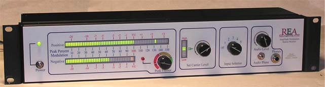
When monitoring in headphones at the same time your are speaking on the air, it is vitally important that you be able to change the phase of the headphones. Due to bone conduction, you will always hear your own voice, even when your ears are closed off, while you are speaking. You want the sounds coming from the headphones to be in phase with the sounds your ears are receiving directly from your voice. There is a dramatic difference in the sound you will hear through headphones, monitoring your own voice, when the sound from the headphones is in phase or out of phase with what you hear through bone conduction. Be sure your modulation monitor or monitoring system (if you build your own) has a headphone phase switch! |
Getting more helpThe AM community is ready to lend assistance, advice, etc. if you need it, in getting your station set up. Check the Class E forum, AM Fone and the AM Window web sites for more details. |