Home
Class E Overview and
Theory of Operation
Output Circuit Values & MOSFET ratings
High Power & Harmonic Reduction
Construction Overview
Simple 400 Watt
RF Amp for
80 meters
Using a lower power
transmitter as an
RF source (A to D converter)
Pulse Width Modulator and power supply
24 MOSFET RF Amplifier - Step by Step
Analog Modulator (Class H) and power supply
Overall Schematic of a complete modulator/power supply
![]()
.A Simple VFO for 80 and 160 Meters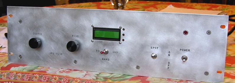 2 Band VFO built by WA1SSJ This VFO is simple to build and is quite stable. The VFO produces a two phase output (2 outputs, push pull), making it well suited to supplying a signal to either single ended RF amplifiers, where only one of the outputs is used, or to balanced (push-pull or single ended push-pull) RF amplifiers where both outputs would be used. By using a frequency counter, the need for a mechanically calibrated dial is elminated, significantly recucing construction complexity. The VFO includes RF waveform duty-cycle control (allows adjustment of the pulse width of the "on" pulse), facilitating maximum efficiency in the class E RF amplifier, and providing a means of adjusting the balance between modules in single ended push pull class E amplifiers.
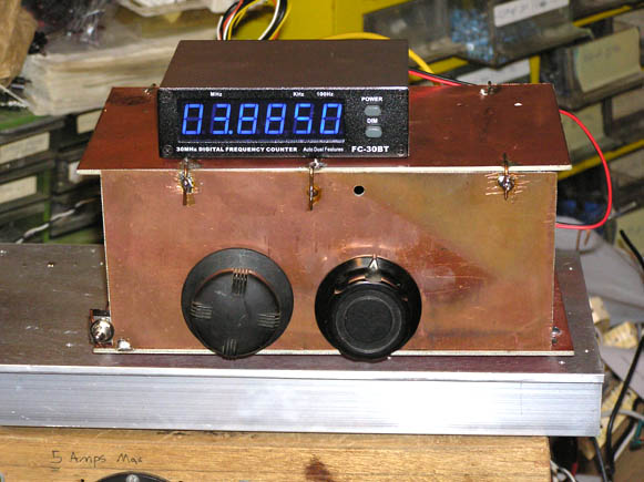 2 Band VFO built by WA1QIX The frequency counter is an inexpensive "Citizen's Band" counter. These counters may be found on Ebay and other electronic equipment vendors. Most any frequency counter may be used. Schematics:VFO Schematic (.PDF)
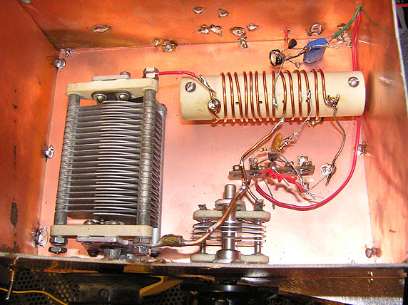
To the right:Inside of the VFO showing all of the oscillator and buffer components. The large capacitor to the left is the coarse frequency adjustment, and the smaller capacitor is the fine frequency adjustment.
Circuit DetailsReferring to the VFO Schematic, the circuit uses a Hartley oscillator operating between approximately 7 to 8 mHz. The buffered oscillator output is then divided by 2 for 75 meter operation or divided by 4 for 160 meter operation. The oscillator runs constantly (at 7 to 8 mhz) when the VFO is turned on. The frequency dividers are turned off during receive, eliminating any signal "bleed" at the operating frequency during receive. By leaving the 7 mHz master oscillator running all the time, there is no transmit-receive oscillator warmup drift.The analog output from the buffer stage (Q2) is fed to a J-K flip flop. The flip flop will change state on each rising edge of the oscillator output signal. This will guarantee a symmetrical output waveform regardless of the symmetry of the output from the master oscillator itself. On 75 meters, the oscillator output is divided one time (by 2), and on 160 meters the oscillator output is divided by 4. The dividers feed a simple pulse shaping circuit, allowing adjustment of the duty cycle ("on time") of the output waveform for each phase. From the pulse shaping circuitry, the RF signals are fed to two IXDD414 driver ICs, providing a 12V, low impedance output suitiable for driving terminated (50 ohm) coax cable.
The VFO includes a relay that can be used to enable the operation of other
circuits or relays. When the VFO is producing output, the relay closes. When
the VFO is in standby, the relay will open. There is a small delay between the
time when the VFO is put into standay, and when it actually goes to standby. This
delay allows the builder to configure a transmit/receive system that allows
output and other circuits to become inactive before the VFO output stops. The
VFO relay opens only when the VFO output actually stops. Ideally, the VFO
relay should be used to prevent the high voltage power supply from supplying
power, should the VFO not be enabled for whatever reason.
Note: The VFO relay should not be
the only source of control for the high voltage supply, rather the relay should be
in series with the coil of the high voltage power supply control relay(s) as
ONE of the conditions for high voltage supply operation.
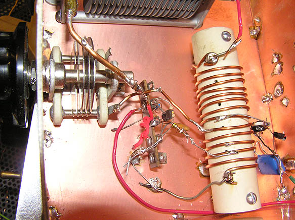
To the right: Closeup of the inside of the VFO. Note the construction of the "gimmick" capacitor. |
Frequency CounterThe frequency counter shown is a simple and inexpensive counter, originally designed for use in conjunction with a Citizen's Band Transceiver. This counter includes an external input, allowing the counter to be used for general purpose applications. This makes it quite suitable for use with this VFO. Power for the counter (+12V) is taken from the VFO's +12V power supply, since the counter uses very little power.
.
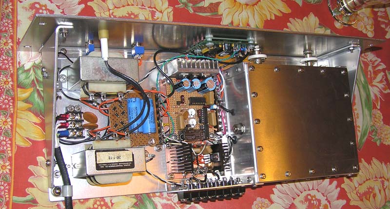
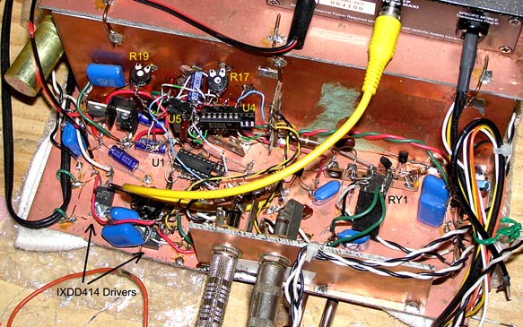
To the right: Back of the VFO showing the J-K flip flop (divider), the pulse shaper circuits (U4, U5, etc.), the IXDD414 outputs, the power supply regulators, the failsafe relay, the frequency counter output stage and other circuits. The yellow wire in the foreground is connected to the frequency counter input. |
Construction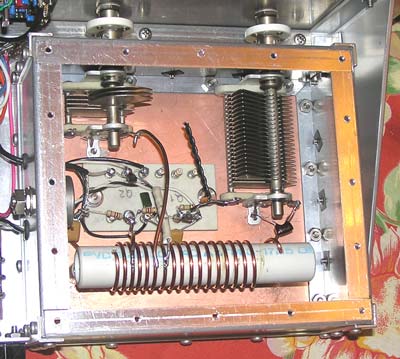
To the left The inside of the WA1SSJ VFO implementation. The aluminum box was constructed from individual panels, joined by angle stock and held together with many screws and nuts. This type of construction makes a very mechanically stable VFO.
|
|
The VFO should be constructed in a mechanically stable enclosure. Thick aluminum
or copper enclosure parts should be used, as even very small movements of the sides,
top, bottom or back will cause the VFO to "wobble".
Although the leads should
be as short and as as stiff as possible, the layout is not particularly critical.
The buffer stage (Q2) should be physically close to the point where the
VFO signal exits the shielded compartment. All power leads entering the
VFO shielded compartment should be bypassed at the point of entry to prevent
stray RF from interfering with the master oscillator. The master oscillator
circuitry including the coil and capacitors should be kept away from other
circuits, and particularly from any wires entering or leaving the shielded
compartment.
All mechanical components should be securely mounted to the VFO cabinetry. The coil should not be placed too close to any of the sides, top or bottom of the VFO cabinet, and the ends of the coil should be at least a coil diameter from the cabinet. |
 Above, the back of the WA1SSJ VFO. Proper attention to wiring details, and a well thought out layout make a very neat, professional package. Important: Because all components in the VFO are operating at RF, including the divider IC and the signal sensing and most of the fail-safe relay control circuits, all of the circuitry should be built over a solid copper ground plane. Ground and bypass capacitor leads should be kept relatively short. All outputs should be carried on properly terminated, shielded cable. |
Adjustment and Testing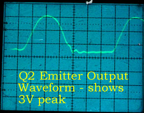 Once the operation of all of the VFO power supplies is verified, the first
step in adjusting the VFO is to ensure the oscillator is setup correctly. If
the VFO will not oscillate, make sure there are no wiring errors, and that
the "gimmic" capacitor is large enough to ensure proper coupling.
Once the operation of all of the VFO power supplies is verified, the first
step in adjusting the VFO is to ensure the oscillator is setup correctly. If
the VFO will not oscillate, make sure there are no wiring errors, and that
the "gimmic" capacitor is large enough to ensure proper coupling.
Assuming the oscillator is oscillating correctly, look at the VFO output across R11, and adjust R5 for the waveform shown to the left.
|
 With the VFO in the "spot" position, use an oscilloscop to verify
that both outputs are functioning. Adjust R17 and R19 to obtain the desired
on-time duty cycle. A good duty cycle for push-pull or single ended push-pull
is 40% on, 60% off. Once connected to an operating class E RF amplifier,
the duty cycle can be further adjusted to obtain optimum efficiency,
and balance between modules (if more than one RF module is used).
With the VFO in the "spot" position, use an oscilloscop to verify
that both outputs are functioning. Adjust R17 and R19 to obtain the desired
on-time duty cycle. A good duty cycle for push-pull or single ended push-pull
is 40% on, 60% off. Once connected to an operating class E RF amplifier,
the duty cycle can be further adjusted to obtain optimum efficiency,
and balance between modules (if more than one RF module is used).
|
 The frequency counter takes a 1V peak to peak signal, and the input impedance of this
counter appear to be relatively low. To the end, a seperate filtered buffer
stage (Q5) is included solely for the purpose of driving the frequency counter.
The frequency counter driver output is filtered to remove high frequency signals that
may cause false triggering of the counter.
The frequency counter takes a 1V peak to peak signal, and the input impedance of this
counter appear to be relatively low. To the end, a seperate filtered buffer
stage (Q5) is included solely for the purpose of driving the frequency counter.
The frequency counter driver output is filtered to remove high frequency signals that
may cause false triggering of the counter.