Home
Class E Overview and
Theory of Operation
Output Circuit Values & MOSFET ratings
High Power & Harmonic Reduction
Construction Overview
Simple 400 Watt
RF Amp for
80 meters
Using a lower power
transmitter as an
RF source (A to D converter)
Pulse Width Modulator and power supply
24 MOSFET RF Amplifier - Step by Step
Analog Modulator (Class H) and power supply
Overall Schematic of a complete modulator/power supply
![]()
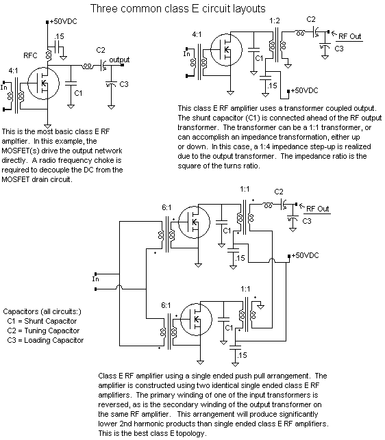
The RF amplifier: circuit values, MOSFET ratings and operational conditionsThis section describes the various components used in class E RF amplifiers, and how the values of these components affect amplifier operation. Note: Complete class E RF amplifiers are presented on this site, with all circuit and component values specified. These are tested, proven circuits that have been reproduced many times. If you are building a class E amplifier with a different configuration (numbers of MOSFETs, frequency, etc.), it is possible to figure your RF values by an educated guess and check method, using the component values presented here as a rough guide, or via complex calculations. There is some very good design software available that will calculate the component values for common class E amplifier layouts. Check the Design Tools Section for more information.
The Shunt CapacitorThe function of the shunt capacitance is to reduce the peak voltage appearing across the MOSFET when the device is in the off state, and to spread the width of the "off" pulse. The shunt capacitor is also part of the output matching network. This capacitor must be a high quality, high current component. Typically, multi-layer ceramic capacitors work best, however silver-mica capacitors can also be used in this function. The actual value of the shunt capacitor is important for a couple of reasons. First, if the capacitance is too small, you will see a very high RF peak voltage across your MOSFETs. If the value is too large, the efficiency can suffer. This is not an extremely critical value, and your transmitter will work over a wide range of values. A good rule of thumb for FQA11N90 MOSFETs operating at 45 volts, approximately 1 to 1.2 Amperes for MOSFETs in parallel is as follows:
The shunt capacitor value is correct if the peak RF voltage across the MOSFETs during the "off" cycle is around 3.5 times the DC voltage applied to the stage. If the voltage is higher than this value, you may need to increase your shunt capacitor. The best capacitors as of this writing for shunt capacitor use are Multi Layer Ceramic capacitors made by American Technical Ceramics. The 100C series of capacitors from ATC is particularly good. AVX also makes good, high current multilayer ceramic capacitors. Tuning Capacitor Voltage Rating The series tuning capacitor is subject to very high RF voltage, and several thousand volts is not uncommon. Using a lower inductance and higher capacitance in the resonant circuit will reduce the voltage across the tuning capacitor somewhat. A useful rule of thumb for figuring the tuning capacitor voltage rating is 3 to 5 times the peak to peak RF voltage fed to the resonant network plus a safety factor. As an example, you normally expect to see 500 volts peak across your class E MOSFETs, and if you have 2 modules in series in your RF amplifier, you will see 1000 volts peak to peak across the secondary of the transformer, which is the input voltage to the resonant network. The tuning capacitor should have a 3000V or better, a 4000V or 5000V rating. MOSFET Voltage RatingThe peak voltage across the MOSFETs is going to be a little less than 4 x the DC applied voltage for a proper class E transmitter. This will vary somewhat with tuning and your exact circuit. If you have very low, or NO shunt capacitor, the ratio of peak RF voltage to applied DC can be 6x or 8x the DC or MORE. For class e transmitters with proper shunt capacitors, figure 4x the DC, plus a safety factor. If you're running 40 @ 5 amps of carrier, and expect to modulate 150% positive, your power supply voltage is going to be 100 volts. So, your MOSFETs are going to see 400V at a minimum. Use AT LEAST a 600 volt MOSFET, and I would personally use an 800V or 1000V MOSFET in this application. MOSFET Current RatingThe current rating of the MOSFET should be at least three times the Maximum DC current expected. Again, if you're running 40 @ 5 amps of carrier, and expect to modulate 150% positive, your power supply voltage is going to be 100 volts. Base your calculations based on 100V. So, your DC current at 150% positive modulation will be 12.5 amps. Figure your total MOSFET current rating (all MOSFETs in parallel) should be at least 36 amps. Your efficiency will be better if you run less current, or use MOSFETs with a higher current rating (or MOSFETs in parallel). The R D-S on (Resistance Drain-Source when the MOSFET is on) becomes a big factor, particularly as currents increase. |